Safety Boost Warning Light
No more "Am I in safety boost?"-questions. Now you'll be sure and you'll be warned when it happens.
Note: This is for people
that are a bit handy with a soldering iron and can read schematics.
Since I mounted the AVC-R boost controller I had a unpleasant feeling about the lack
of the factory safety-boost mode.
I'm sure this is something that I share with many of you.
I figured that a warning light is necessary.
At first I connected a
relay in place of the waste gate solenoid to monitor its status. This had one drawback
though, the light came on every time I let of the throttle.
The problem is that the ECU disengages the solenoids when the throttle position
voltage is below ~0.75V.
The solution was to use a comparator to check the throttle position before allowing
the warning light to lit.
Now the warning light comes on only if the throttle is above 0.85V and the waste gate
solenoids are OFF.
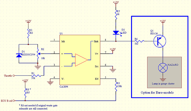
Here's the schematics:

The key component is the
CA3094 (Harris) Power Switch/Amplifier which costs only a couple of bucks. It minimizes
the number of components needed.
The "Throttle" signal is compared to the preset threshold level (0.85V) on
pin 2. You can of course replace the pot R2 with 2 resistors.
The Zener diode D1 is for voltage stabilization since the +12V is not stable.
If "Throttle" is higher than the threshold then the output on pin 8 gets
grounded causing the light to lit.
The enable pin (5 ) can disable the warning light when it's low (no safety boost).
This happens when the throttle is above 0.75V and the ECU activates the waste gate
solenoids by grounding the control output (light blue wire on pin 25 on ECU, see the
diagram HERE).
One note though, the light will lit also when the engine is to cold or to warm, because this is what triggers safety boost besides the knock sensor. This is good though...Now you will know when the engine is warmed up!
As for the indicator
itself, I used an existing lamp in the gauge cluster. It's the "Hazard"
indicator that blinks when the hazard lights are on. This light is only on the European
models, according to the schematic diagram in the Service Manual. Maybe you could use some
other indicator on the US models? You can also use a LED as shown in the schematics above.
The picture below shows the connector on the hazard switch. Cut the red wire from the
connector and put some isolation on it. The other end of the wire goes to the hazard lamp
in the gauge cluster.
The output from this circuit can also be used to drive a relay (max 100mA on the CA3094!) that cuts the power from the boost control solenoid of your boost controller. This will give you the safety boost mode back! Personally I'm just using the warning light.
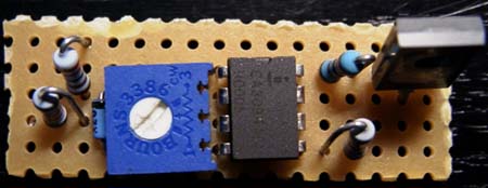
Here's how the circuit looks like when mounted on a universal PCB:

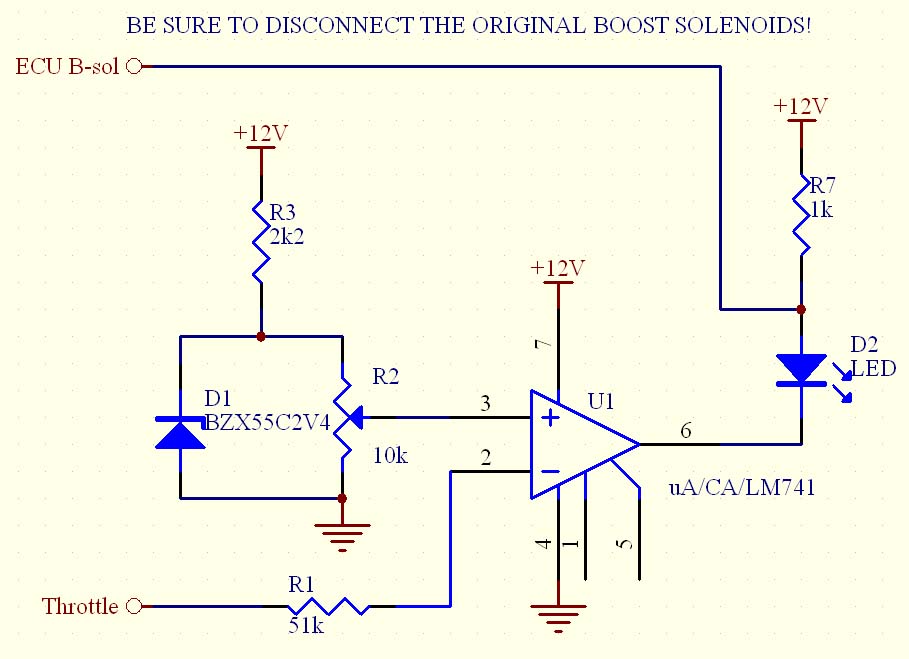
Alternative solution, using the 741 OP-Amp
Due to problems with the
availability of the CA3094 OP-Amp, a new solution was needed.
This one requires the original boost solenoids to be disconnected.

For those still running the original solenoids, connect the R7 in series between the ECU Boost Solenoid wire and the D2 LED.
Note: I didn't have time to test the 741 solution in practice but it should work fine.
Have fun!
Maciej